3D
Display markers, entities, camera images, meshes, URDF models, and more in a 3D scene.
Visualization
Visualizing objects in the 3D scene correctly requires your data to conform to certain conventions. When you enable a topic for visualization, the 3D panel will subscribe to the topic, receive messages on the topic in log time order (see: playback), and visualize the latest message on each enabled topic using the timestamp or header.stamp (ROS) information in the message.
To render objects into the scene, there must exist a transform path from the object's coordinate frame to the display frame at or before the timestamp of the object being visualized. For objects this timestamp comes from the timestamp or header.stamp (ROS) field within the message, NOT the log time (aka receive time). Like other messages, transform messages are received in log time order but stored and accessed by the timestamp or header.stamp field within the message.
This convention allows your robot to receive sensor data and transform state, perceive and identify objects in the scene, and produce a message describing the scene at some time that relates to the sensor data or processing rather than the log time which might come later. This provides a mechanism for more accurately representing the scene as the robot may have experienced it.
Supported messages
The 3D panel can visualize an assortment of different messages.
To visualize a topic, the messages on that topic must conform to one of the known message schemas listed below.
Camera field-of-view
Calibration parameters for your scene's camera.
| framework | schema |
|---|---|
| ROS 1 | sensor_msgs/CameraInfo |
| ROS 2 | sensor_msgs/msg/CameraInfo |
| Custom | foxglove.CameraCalibration |
Grid
2D colored grids.
| framework | schema |
|---|---|
| ROS 1 | nav_msgs/OccupancyGrid |
| ROS 2 | nav_msgs/msg/OccupancyGrid |
| Custom | foxglove.Grid |
foxglove.Grid settings
| field | description |
|---|---|
| Color mode | One of: Flat: solid color Color map: pre-defined color palette Gradient: smooth transition between two custom colors RGBA (separate fields): use embedded color from each cell's red, green, blue, and alpha fields (see below) |
| Flat color | Only shown if "Color mode" is set to "Flat"; hex code for color of each cell |
| Color field | Only shown if "Color mode" is not set to "Flat"; numeric field in message used for coloring logic |
| Color map | Only shown if "Color mode" is set to "Color map"; "Turbo" (Google) or "Rainbow" (RViz); for mapping "Color field" values to colors |
| Opacity | Only shown if "Color mode" is set to "Color map" or "BGR (packed)"; sets alpha value for all cells |
| Value min | Only shown if "Color mode" is not set to "Flat"; minimum value used to normalize incoming grid's "Color field" values |
| Value max | Only shown if "Color mode" is not set to "Flat"; maximum value used to normalize incoming grid's "Color field" values |
| Elevation field | Optional field to displace each grid cell in the Z axis; if not set, elevation is 0 for all cells |
| Interpolation method | Only shown if "Elevation" is set; either Linear or Nearest Neighbor. Determines how elevation and color values are sampled spatially across the grid. |
| Show lines | Only shown if "Elevation" is set; whether to render subtle grid cell borders |
| Line color | Only shown if "Show lines" is enabled; color of the cell grid lines |
| Lighting | Only shown if "Elevation" is set; enables shading from simulated directional lighting, based on elevation surface normals |
| Frame lock | "On" means the grid is locked to the frame specified by its frame_id, and will move as that frame's transforms change. "Off" means the grid is relative to the fixed frame and will not move after it is first displayed. |
RGBA (separate fields) color mode
Each cell can contain color information in four separate fields, named red, green, blue, and alpha, of any numeric type:
- Floating-point values — 0–1 range
- Unsigned integer values — Maximum possible range (e.g. 0–255 for a
UINT8field) - Signed integer values —
-maxtomax(e.g. −127 to 127 for anINT8field; a value of −128 is treated as identical to −127)
nav_msgs/OccupancyGrid settings
| field | description |
|---|---|
| Color mode | One of: Costmap: pre-defined RViz color palette. Cannot customize settings further. Custom: custom color palette using settings below |
| Min color | Color corresponding to minimum cell value (0) |
| Max color | Color corresponding to maximum cell value (100). Note that cells with value exactly 100 are displayed as fully transparent. |
| Unknown color | Color corresponding to unknown cell value (−1) |
| Fallback color | Color corresponding to cell values that fall outside the range from −1 to 100 |
| Frame lock | "On" means the grid is locked to the frame specified by its frame_id, and will move as that frame's transforms change. "Off" means the grid is relative to the fixed frame and will not move after it is first displayed. |
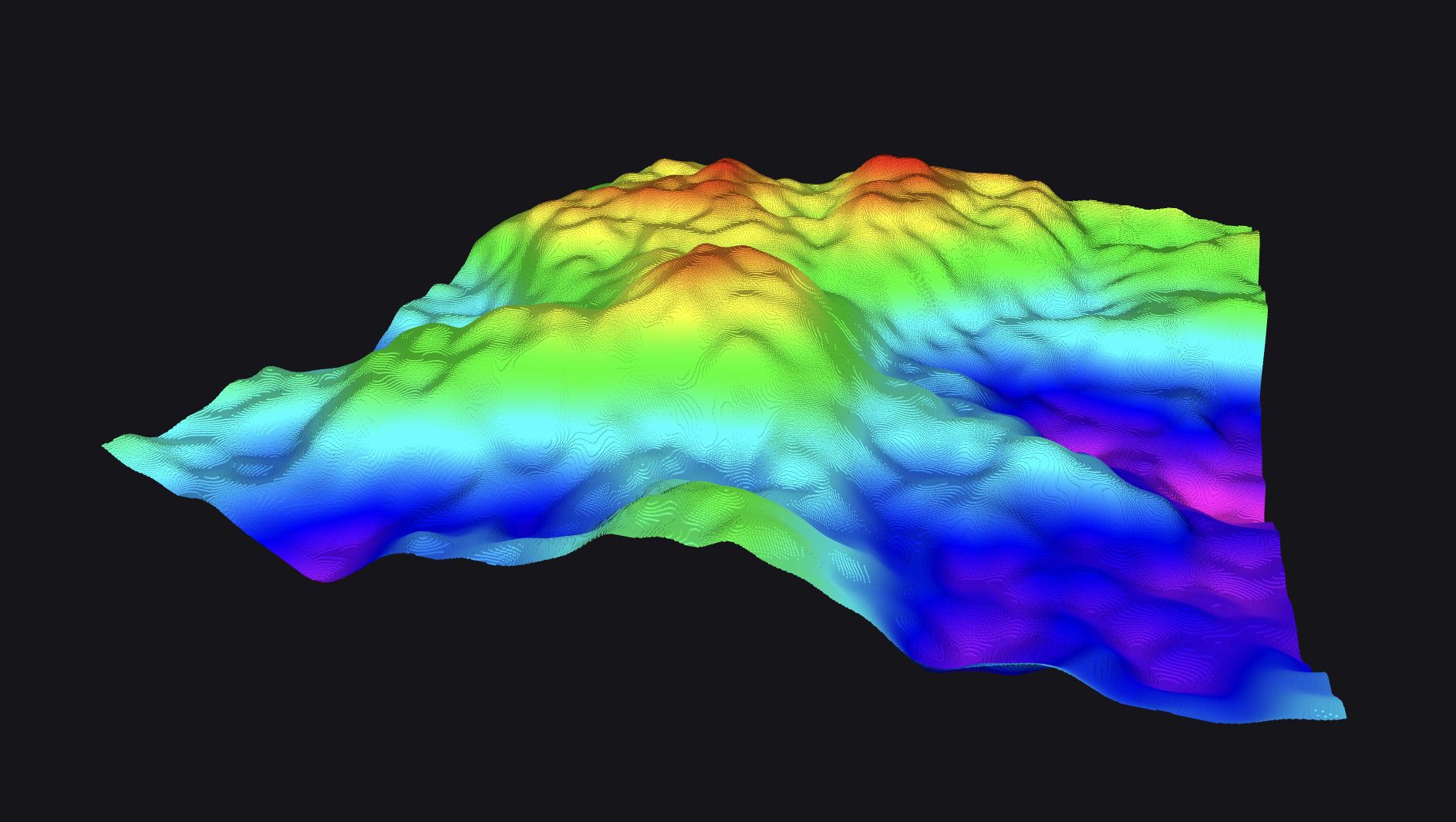
Grid Map
A 2D grid of cells containing multiple layers of float values, commonly used for representing terrain, traversability, and other spatial data. Each layer can represent different kinds of data such as height, cost, or classification.
| framework | schema |
|---|---|
| ROS 1 | grid_map_msgs/GridMap |
| ROS 2 | grid_map_msgs/msg/GridMap |
Settings
| field | description |
|---|---|
| Interpolation method | Sampling method used between grid cells. Options: "Linear" or "Nearest Neighbor". |
| Elevation layer | Layer used to determine height. Must be present in the message's layers array. |
| Color layer | Optional. Layer used to determine color. If not specified, a "Rainbow" color map will be applied. |
| Gradient | Only shown if "Color layer" is specified and not set to "Rainbow". Defines the color gradient used to map values to colors. |
| Show lines | Whether to draw outline grid lines between each cell. |
| Line color | Only shown if "Show lines" is enabled. Sets the RGBA color of the grid lines. |
| Lighting | Whether to enable dynamic lighting on the grid surface. |
Layer rendering
Each cell in the grid can store multiple scalar values across different layers. For visualization, you typically select one layer as the elevation map and optionally another as a color layer. All layers are represented as aligned 2D float arrays with a shared grid layout.
When a color layer is set to "Rainbow", values are colorized using a predefined color map. If a custom layer is selected, the "Gradient" field allows you to map values to a user-defined gradient.
Grid lines and lighting are optional and help enhance visualization for elevation structure or separation.
Image
Images displayed in the 3D scene, using the corresponding Camera field-of-view messages.
| framework | schema |
|---|---|
| ROS 1 | sensor_msgs/Image |
| ROS 2 | sensor_msgs/msg/Image |
| ROS 1 | sensor_msgs/CompressedImage |
| ROS 2 | sensor_msgs/msg/CompressedImage |
| Custom | foxglove.RawImage |
| Custom | foxglove.CompressedImage |
Laser scan
A single scan from a planar laser range-finder.
| framework | schema |
|---|---|
| ROS 1 | sensor_msgs/LaserScan |
| ROS 2 | sensor_msgs/msg/LaserScan |
| Custom | foxglove.LaserScan |
ROS polygons
Timestamped polygons made up of a series of connected points.
| framework | schema |
|---|---|
| ROS 1 | geometry_msgs/PolygonStamped |
| ROS 2 | geometry_msgs/msg/PolygonStamped |
ROS markers
Similar to scene entities, these Marker messages describe primitive shapes or meshes.
| framework | schema |
|---|---|
| ROS 1 | visualization_msgs/Marker |
| ROS 2 | visualization_msgs/msg/Marker |
| ROS 1 | visualization_msgs/MarkerArray |
| ROS 2 | visualization_msgs/msg/MarkerArray |
Mesh markers
Markers with a mesh_resource field support the following URL schemes:
http(s)://package://(Desktop app only)file://(Desktop app only)
And file formats:
- glTF
- STL
- COLLADA
- Wavefront OBJ
glTF (.glb)
This is the preferred format, as it enjoys the best performance of all supported file types.
Binary glTF files bundle all required assets into a single file, with support for embedded meshes, compression, and the same physically-based material system used in Foxglove. As a result, your model should appear in Foxglove similarly to how it appears in other 3D programs.
STL (.stl)
STL files are well supported in Foxglove, but lack some of glTF's visualization features. The main advantage to STL is the ability to share the same files between your hardware manufacturing process and robot visualization tooling.
STL was designed for 3D printing and CAD applications, and does not include materials or hierarchies of meshes. While they can be represented in a binary encoding, STL files are commonly represented with ASCII characters, which leads to larger files.
COLLADA (.dae)
As a predecessor to glTF, COLLADA has a similar feature set. With that said, it does have larger XML-based files, no compression, and additional processing overhead.
There is a bug in RViz where the up-axis metadata is ignored, resulting in incorrect orientations for many .dae files in ROS environments. To work around this, the 3D panel has a Ignore COLLADA <up_axis> setting to toggle between observing the <up-axis> tag or ignoring it like RViz.
Wavefront OBJ (.obj)
OBJ is a simple ASCII format predating all other supported formats. It has large file sizes, no material support, no mesh hierarchies, no compression, and additional processing overhead.
Material support was added to the OBJ format as separate .mtl files, which Foxglove does not read.
Path
An array of timestamped poses in a named coordinate frame, denoting an object's path through space.
| framework | schema |
|---|---|
| ROS 1 | nav_msgs/Path |
| ROS 2 | nav_msgs/msg/Path |
| Custom | foxglove.PosesInFrame |
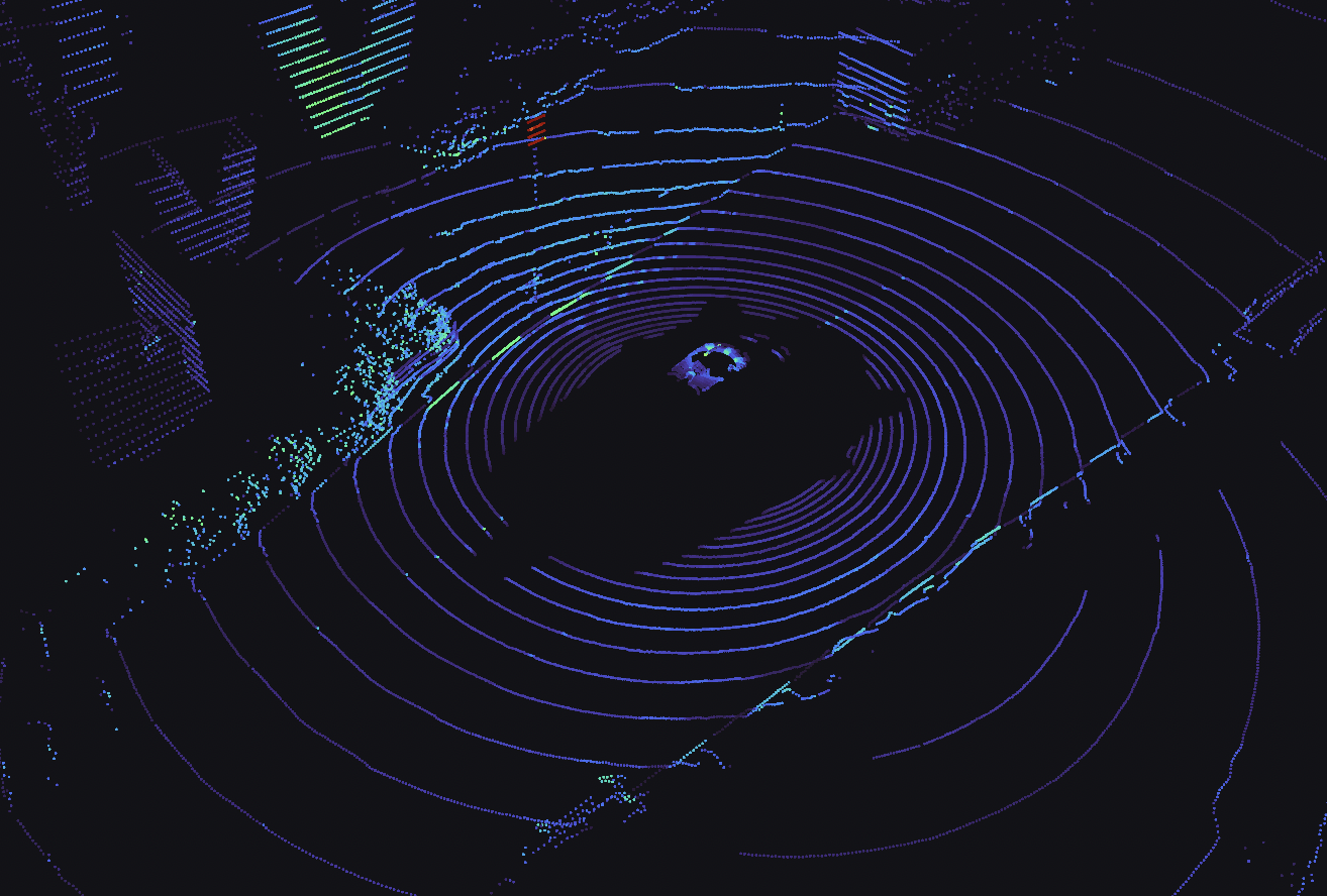
Point cloud
A collection of N-dimensional points, which may contain additional fields with information like normals, intensity, etc.
| framework | schema |
|---|---|
| ROS 1 | sensor_msgs/PointCloud2 |
| ROS 2 | sensor_msgs/msg/PointCloud2 |
| Custom | foxglove.PointCloud |
Settings
| field | description |
|---|---|
| Point shape | Shape of each rendered point: "Circle", "Square", or "Cube". Default: "Circle". |
| Point size | Size of each rendered point in pixels. Only shown when the point shape is "Circle" or "Square". |
| Cube size | Size of each cube in 3D scene units. Only shown when the point shape is "Cube". |
| Show outline | Toggle whether to display wireframe outline around cubes. Only shown when the point shape is "Cube". Default: "Off" |
| Decay time | Duration of time (in sec) that each point stays rendered |
| Color mode | One of: Flat: solid color Color map: pre-defined color palette Gradient: smooth transition between two custom colors BGR (packed): sensor_msgs/PointCloud2 only; use embedded color from each point's rgb field (see below)BGRA (packed): sensor_msgs/PointCloud2 only; use embedded color from each point's rgba field (see below)RGBA (separate fields): foxglove.PointCloud only; use embedded color from each point's red, green, blue, and alpha fields (see below) |
| Flat color | Only shown if "Color mode" is set to "Flat"; hex code for color of each point |
| Color field | Only shown if "Color mode" is not set to "Flat"; value used for "Color map" coloring logic; any numeric field in message such as x, y, z, <distance> (L2 norm of coordinates), or custom defined field |
| Color map | Only shown if "Color mode" is set to "Color map"; "Turbo" (Google) or "Rainbow" (RViz); for mapping "Color field" values to colors |
| Opacity | Only shown if "Color mode" is set to "Color map" or "BGR (packed)"; sets alpha value for all points |
| Value min | Only shown if "Color mode" is not set to "Flat"; minimum value used to normalize incoming points' "Color field" values |
| Value max | Only shown if "Color mode" is not set to "Flat"; maximum value used to normalize incoming points' "Color field" values |
| Stixel view | Visualize points as stixels that extend from the point's z location to 0 |
RGBA color modes
When using the "BGR (packed)", "BGRA (packed)", and "RGBA (separate fields)" color modes, your point cloud message must contain certain fields to display color information for each point.
RGBA (separate fields)
For foxglove.PointCloud messages, each point can contain color information in four separate fields, named red, green, blue, and alpha, of any numeric type:
- Floating-point values — 0–1 range
- Unsigned integer values — Maximum possible range (e.g. 0–255 for a
UINT8field) - Signed integer values —
-maxtomax(e.g. −127 to 127 for anINT8field; a value of −128 is treated as identical to −127)
BGR (packed) and BGRA (packed)
For sensor_msgs/PointCloud2 messages, each point can contain color information in a single field named rgb or rgba:
- Must use a 4-byte type from sensor_msgs/PointField (
UINT32, value 6, is recommended) - Each red, green, blue, and alpha value is represented by one byte in the 0–255 range
- Bytes must be packed in
[0xBB, 0xGG, 0xRR, 0xAA]order (i.e.(0xAA << 24) | (0xRR << 16) | (0xGG << 8) | 0xBBin little-endian order). This order is compatible with RViz.
If using the "BGR" mode, the alpha value must still be present, but is ignored.
Pose
Poses in a named coordinate frame.
| framework | schema |
|---|---|
| ROS 1 | geometry_msgs/PoseArray |
| ROS 2 | geometry_msgs/msg/PoseArray |
| ROS 1 | geometry_msgs/PoseStamped |
| ROS 2 | geometry_msgs/msg/PoseStamped |
| Custom | foxglove.PosesInFrame |
Scene entity
A collection of primitive shapes (cubes, spheres, text, meshes, lines, etc) used to display anything from a basic bounding box to a complex 3D decision tree or road network.
Scene entities must be wrapped in a SceneUpdate message.
| framework | schema |
|---|---|
| Custom | foxglove.SceneEntity |
| Custom | foxglove.SceneUpdate |
Settings
| field | description |
|---|---|
| Color | Render all entities under this topic with this color, overriding colors defined in the entities. |
| Show outlines | Display a wireframe outline around rendered entities. |
| Selection variable | Set a global variable with this name to the selected entity ID. |
| Vertex normals | Toggle calculation of vertex normals. Normals improve lighting and visual appearance but incur a significant performance penalty in some cases. |
Transforms
A transform (translation and rotation) between two reference frames in 3D space.
| framework | schema |
|---|---|
| ROS 1 | tf/tfMessage |
| ROS 1 | tf2_msgs/TFMessage |
| ROS 2 | tf2_msgs/msg/TFMessage |
| Custom | foxglove.FrameTransform |
Velodyne scan
Velodyne Lidar scan packets from the Velodyne ROS driver or the Foxglove desktop app's Velodyne connection.
| framework | schema |
|---|---|
| ROS 1 | velodyne_msgs/VelodyneScan |
| ROS 2 | velodyne_msgs/msg/VelodyneScan |
Video
Compressed videos displayed in the 3D scene, using the corresponding Camera field-of-view messages.
| framework | schema |
|---|---|
| Custom | foxglove.CompressedVideo |
Voxel Grid
A 3D volumetric grid used to represent occupancy information in a spatial environment, typically used in robot navigation and obstacle avoidance. Each voxel can be marked (obstacle), present (observed), or unknown, and the grid is used to compute traversability.

| framework | schema |
|---|---|
| ROS 1 | costmap_2d/VoxelGrid |
| ROS 2 | nav2_msgs/msg/VoxelGrid |
Settings
| field | description |
|---|---|
| Color mode | How to color each voxel. Options: • By type (based on occupancy classification) • Gradient (numeric field mapped to a gradient) • Rainbow (predefined colormap) |
| Gradient | Only shown if "Color mode" is set to "Gradient". User-defined color mapping for voxel values. |
| Marked and present | Only shown if "Color mode" is set to "By type". RGBA color for voxels that are both marked and present. |
| Present | Only shown if "Color mode" is set to "By type". RGBA color for voxels that are present but not marked. |
| Marked | Only shown if "Color mode" is set to "By type". RGBA color for voxels that are marked but not present. |
| Use lighting | Enables lighting for voxel shading in 3D view. |
Voxel classification
When using By type coloring:
- Marked voxels represent obstacles or areas flagged as non-traversable.
- Present voxels represent observed but unmarked areas.
- Marked and present voxels are both observed and flagged.
Each voxel is rendered as a cube in 3D space and can be shaded based on lighting settings. The resolution and origin of the grid are defined in the message metadata (resolutions, origin, and data fields).
Settings
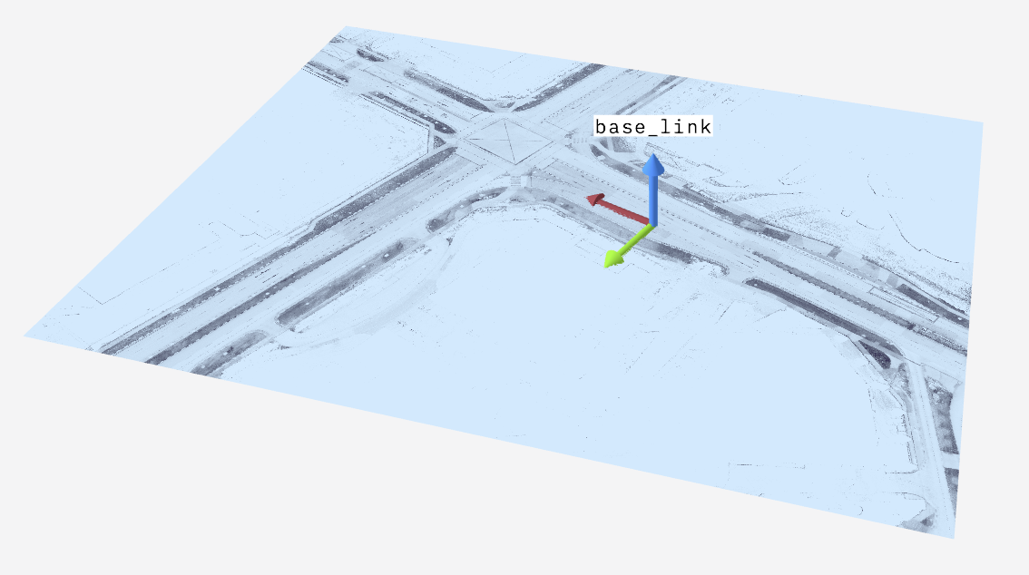
Frame
Select your 3D scene's display frame and follow mode.
| field | description |
|---|---|
| Display frame | The coordinate frame for rendering the scene. The camera position and orientation are relative to the origin of this frame. To render a scene element, you need a transform from its frame to the selected display frame. If its frame is the display frame, no additional transform is needed. |
| Follow mode | The viewport following behavior during playback:
|
Scene
Configure generic rendering properties and viewport properties.
| field | description |
|---|---|
| Show render stats | Display rendering performance statistics in panel |
| Background | Background color of the scene |
| Label scale | Scale factor to apply to all rendered labels |
Ignore COLLADA <up_axis> | Match the behavior of RViz by ignoring the <up_axis> tag in COLLADA files |
| Mesh "up" axis | The direction to use as "up" when loading meshes without orientation info (e.g. STL, OBJ) |
View
Configure the camera settings.
| field | description |
|---|---|
| Sync camera | Sync the camera with other panels that also have this setting enabled |
| Distance | Camera distance from the display frame origin |
| 3D view | Toggles between 3D and 2D views of the scene. The 2D view looks down the z-axis and flattens the scene against the x-y plane. |
| Target | Translational offset from the origin of the display frame |
| Theta | Azimuthal angle offset from the origin of the display frame in degrees |
| Phi | Polar angle offset from the origin of the display frame in degrees |
| Y-axis FOV | Vertical field of view in degrees |
| Near | Near clipping plane distance |
| Far | Far clipping plane distance |
| Log depth | Enable logarithmic depth buffer for more uniform depth precision. May result in rendering artifacts or performance degradation. |
Interaction of log depth and near/far plane settings
The Near, Far, and Log depth settings are interrelated. When using a very small Near value or a large Far value, enabling Log depth may reduce visual artifacts. For example, in the video below:
- The left panel does not use logarithmic depth, and it has a near clipping plane of 1.0. The grids render smoothly, but objects close to the viewer are clipped.
- The middle panel does not use logarithmic depth, and has a near plane of 0.01. The viewer can get closer to objects without clipping, but rendering artifacts (z-fighting) appear between multiple grids.
- The right panel enables the logarithmic depth setting. This avoids z-fighting by providing more depth precision for the grids, while still allowing a near plane value of 0.01 for reduced clipping.
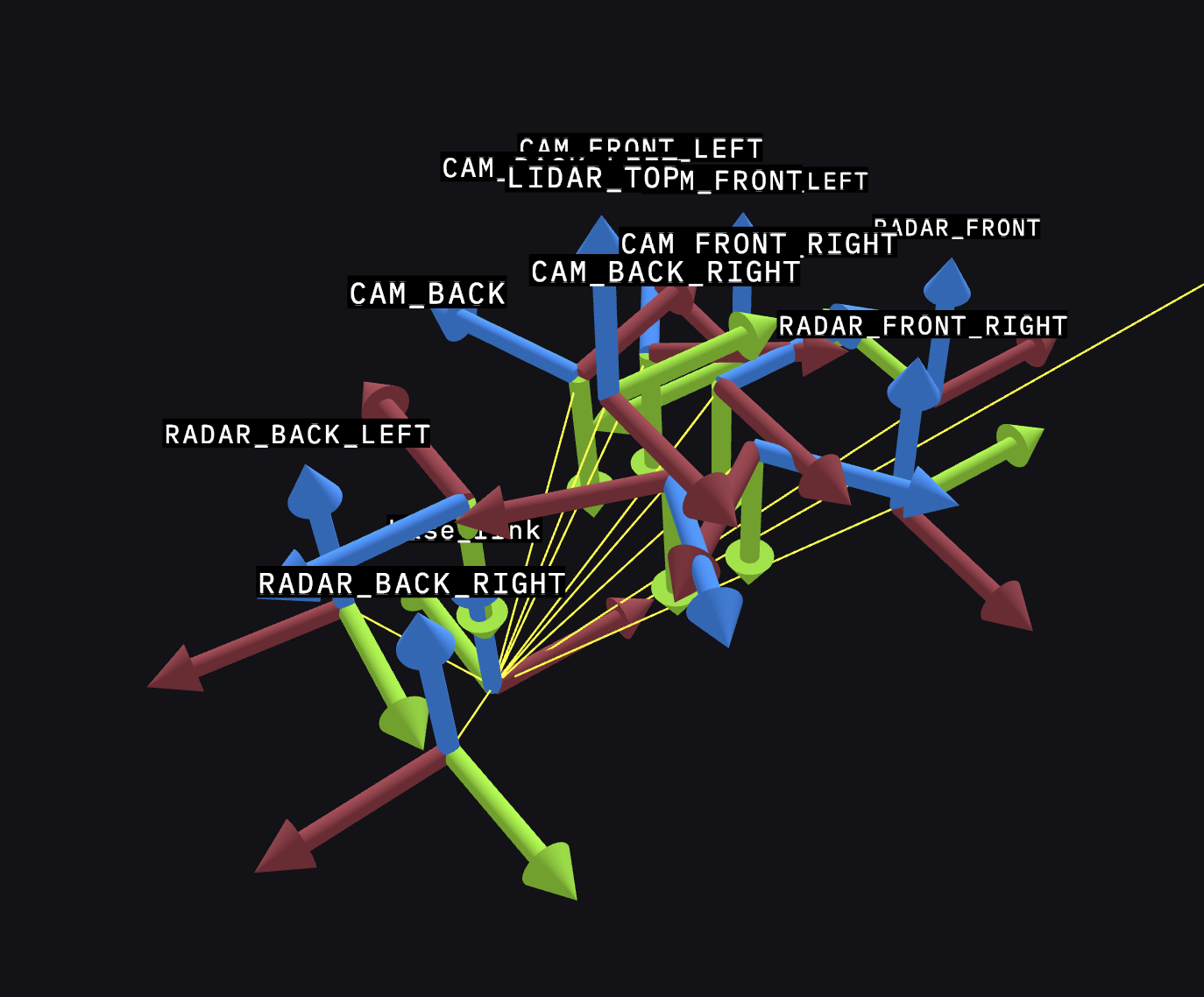
Transforms
A robotics system produces many messages describing its observations of the world around it. These messages may exist in one or more coordinate frames, or on different parts of the robot.
Transforms define the spacial relationships between two coordinate frames at a given time. To render objects into the scene, there must exist a transform path from the object's coordinate frame to the display frame.
Visualize transform frames to debug why elements may not be rendering where expected.
History
The panel stores coordinate frame relationships over time in a transform history store. Each coordinate frame stores up to 10,000 transform messages before it begins to remove the oldest messages as new messages arrive.
Preloading
Transform preloading in the 3D panel ensures an accurate scene by loading transform messages into memory. Transform preloading may impact 3D panel performance during preloading and seeking. You can disable preloading in the 3D panel settings. However, when disabled, the 3D panel may not properly render your scene in certain circumstances where infrequent coordinate frames are involved. To maintain reasonable memory usage, there is an upper limit on the number of transforms that can be preloaded per topic.
Troubleshooting
When working with live sources where time synchronicity cannot be achieved, it is recommended to have the server publish its Time according to the Foxglove WebSocket Protocol. Otherwise if the server time is ahead of the visualization app, certain messages in the 3D panel will display immediately but coordinate frame state can lag behind as the app uses its wall time instead of the server time.
Settings
| field | description |
|---|---|
| Editable | Toggles in-app editing of transform frames. When "on", you can update the Translation and Rotation values to tweak transform frames, see the impact on the scene, and debug how you may want to adjust the frames on your robot. When turned "Off", will revert to original translation and rotation values. |
| Labels | Toggle the display of transform labels. |
| Axis scale | Scale of transform axis (displayed as an arrow marker) |
| Line width | Width of transform (displayed as a line marker) |
| Line color | Color of transform (displayed as a line marker) |
| Enable preloading | Preload transform messages from the data source. |
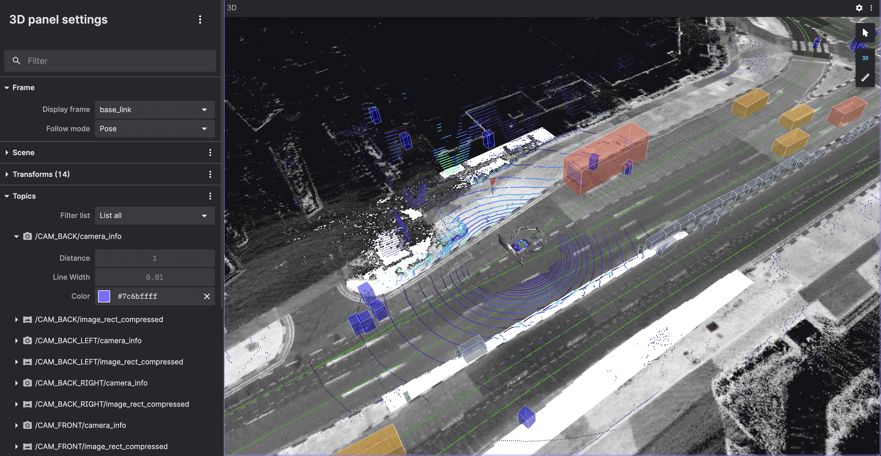
Topics
Lists topics containing supported messages that can be displayed in the scene. Toggle individual topics.
Each topic provides settings to configure how the visualization appears in the scene.
Any topic with messages matching the supported messages will show up in the topics list. Each supported format has format specific visualization settings. These settings will show up under the topic.
Use the top-level menu to toggle all topics. You can toggle any individual topic by click the eye icon next to the topic name.
Custom layers
Custom layers allow you to add visual elements not from your data source.
Use the top-level menu to add custom layers.
Add Grid
A grid is 2D square with a fixed size and number of divisions. You can create any numbers of grids. Grids can be rendered relative to the display frame or any other transform frame.
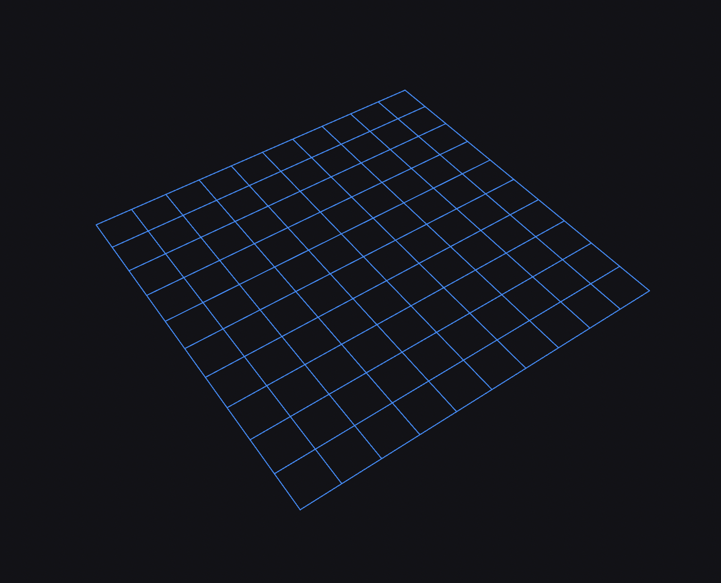
Use the grid layer settings to change the frame, size, color, divisions, and other properties of the grid.
Add URDF
URDF robot models are loaded automatically if your data source supports parameters (i.e. a native ROS 1 or ROS 2 connection) and the /robot_description parameter is set to valid URDF XML.
You can add URDF models with a custom layer. Use each layer's menu to duplicate or delete the custom layer.
| field | description |
|---|---|
| Source | Source of the URDF
|
| Label | (Optional) Label with which the custom layer will appear in the sidebar. |
| Frame prefix | (Optional) Prefix for robot's transforms. Also commonly known as a TF prefix. |
| Display mode | Robot link geometries to display
|
| Color | Fallback color for the URDF model, if the source doesn't contain colors. |
| Opacity | Opacity of link geometries on a scale from 0 (fully transparent) to 1 (fully opaque). |
| Show outlines | Visualize edges of URDF link geometries. |
| Show axis | Visualize coordinate frame axis for each URDF link. |
| Axis scale | Scale of link coordinate frame axis. |
| Joint states | Manually set the joint value of each URDF joint. Disabled when the joint transform is provided by the datasource. |
| Links | Toggle visiblity of each URDF link or set a custom offset with respect to the parent link. The latter is disabled when the transform to the parent link is provided by the datasource. |
Resolution of URDF assets with package:// URLs
Foxglove is able fetch meshes and other assests referenced by package:// in a number of different ways:
- When using the desktop app, package paths can be resolved by finding packages in directories specified by the ROS_PACKAGE_PATH setting
- When using a live connection that supports asset fetching such as Foxglove Bridge, assets can be fetched over the WebSocket connection
- When the URDF is given as http(s) or local file path, package paths can be resolved when the URL or file path contains the package name. Consider the following example where the package name
leo_descriptionis contained in the URDF URL:- URDF URL:
https://raw.githubusercontent.com/LeoRover/leo_common-ros2/humble/leo_description/urdf/leo.urdf.xacro - Asset URL:
package://leo_description/models/Rocker.dae - Resolved asset URL:
https://raw.githubusercontent.com/LeoRover/leo_common-ros2/humble/leo_description/models/Rocker.dae
- URDF URL:
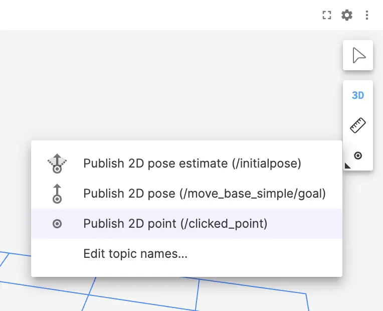
Publish
Configure click-to-publish behavior for the 3D panel.
The click-to-publish feature requires a ROS data source such as the the ROS Foxglove bridge.
| Click-to-publish tool | Corresponding ROS message type |
|---|---|
| 2D pose estimate | geometry_msgs/PoseWithCovarianceStamped |
| 2D pose | geometry_msgs/Pose |
| 2D point | geometry_msgs/Point |
| Field | Description |
|---|---|
| Topic | Topic on which to publish |
| X deviation Y deviation Theta deviation | Only available for the 2D pose estimate tool. Standard deviation values used to create the published covariance matrix. |
Controls and shortcuts
Click any object in the scene to display its relevant details in the selected object popup.
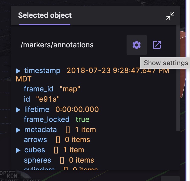
Click the icons next to the topic to open its settings in the sidebar or to display its messages in a new Raw Messages panel.
Selecting an object will set a $selected_id variable to the clicked object's id value, if it has one. For ROS markers and scene entities, you can also set another variable on click.
The panel controls on the right can be used to do the following:
- Select — toggle object select mode
- 3D — Toggle between 3D and 2D views of the scene
- Measure — measure the distance between two points
- Publish — publish a message based on a clicked location in the 3D view
The click-to-publish feature requires a ROS data source such as the the ROS Foxglove bridge.
Activate the currently-selected publish tool by clicking on the icon. Right-click or click and hold to switch between tools.
| Camera movement controls | |
w | Move camera forward |
a | Move camera to the left |
s | Move camera backward |
d | Move camera to the right |
Shift+w | Rotate camera up |
Shift+a | Rotate camera left |
Shift+s | Rotate camera down |
Shift+d | Rotate camera right |
| Scroll | Zoom in and out |
| Drag | Move camera parallel to the ground (x-y plane) |
| Move camera parallel to the screen (enable z-axis) |
Shift + drag, or right-click-drag | Rotate the camera around the target position |
1 | Re-center the camera on the chosen display frame |
3 | Toggle between 2D bird's-eye view and 3D perspective view |
i | Show or hide the object inspector |
Performance troubleshooting
Here are some tips for dealing with performance issues you may encounter.
Hardware acceleration
If you are experiencing poor performance while interacting with the 3D panel, it may be because hardware acceleration is not enabled. Hardware acceleration will significantly improve performance by rendering on the GPU rather than the CPU.
If you're using Google Chrome, you can check that hardware graphics acceleration is enabled by going to chrome://gpu and seeing that "WebGL" and/or "WebGL2" are "Hardware accelerated". If not, go to chrome://settings, search your settings for acceleration and ensure that the "Use graphics acceleration when available" toggle is enabled. If after these steps you still see that WebGL is still not "Hardware accelerated" in chrome://gpu then you might have to investigate platform-specific steps for enabling your GPU.
The desktop app uses Electron (based on Chromium), and should automatically use hardware acceleration when available. If you're seeing issues here, we recommend following the steps above to see if the same issue exists in Chrome. If so, there's a good chance it's affecting our application for the same reasons. Therefore we recommend getting things working in Chrome first, and if the desktop app is still having issues afterward please let us know and we'll look into it.
Some reasons hardware acceleration might be disabled:
- Your graphics drivers are out of date or not installed such that Chrome can make use of them.
- Your system configuration could be unsupported for hardware acceleration in Chrome. A way to solve this is to enable "Override software rendering list" in
about://flags, which can allow Chrome to use hardware acceleration on unsupported systems. This can result in an unstable Chrome experience and is not advised unless necessary.
Video acceleration
If you are experiencing poor performance with the 3D panel while using foxglove.CompressedVideo topics, check that video acceleration is enabled. Docs here.
Triangle primitives
If you have large foxglove.TriangleListPrimitive entities in your scene updates that are added and removed often causing noticable lag, consider toggling the "Vertex normals" setting.
SceneEntity structure
For maximum efficiency, prefer fewer SceneEntities each with many primitives, rather than many SceneEntities each with fewer primitives.