Integrate Luxonis OAK Cameras with Foxglove
You can stream data from Luxonis OAK cameras to Foxglove using DepthAI and the Foxglove SDK. Stream RGB images, colored point clouds, camera calibration, IMU, and transforms, with no ROS required. The camera calculates depth on-device (stereo or neural, chosen with --depth-source), and the SDK streams results over a WebSocket that Foxglove connects to directly.
If you are using ROS, launch your OAK ROS 2 node and follow the ROS 2 documentation to run Foxglove Bridge.
This approach works with all DepthAI-enabled devices. The examples require a stereo camera pair and an IMU — tested with the OAK 4 D. --depth-source neural needs an OAK 4 (RVC4) device; use --depth-source stereo (the default) on older OAK cameras. Use the Python and C++ SDK examples as the reference implementation.
Prerequisites
- A DepthAI-enabled device with a stereo camera pair and an IMU (for example a Luxonis OAK 4 D), connected over USB 3 or Ethernet
- For Python: uv (installs
foxglove-sdkand DepthAI v3 frompyproject.toml) - For C++: the DepthAI C++ library (
depthai-core). If it's in a non-standard prefix, passCMAKE_PREFIX_PATHordepthai_DIRwhen building - On Linux, install the Luxonis udev rules for USB devices
Published Topics
The examples publish these topics:
| Topic | Schema | Contents |
|---|---|---|
/oak/points | foxglove.PointCloud | Colored point cloud in meters |
/oak/rgb/image | foxglove.RawImage | Color video (bgr8) |
/oak/rgb/calibration | foxglove.CameraCalibration | Color-camera intrinsics and distortion |
/oak/imu | JSON (ROS sensor_msgs/Imu-like) | Accelerometer (m/s²) and gyroscope (rad/s) |
/tf | foxglove.FrameTransforms | Transform that orients the camera frame upright |
Installation
- Python
- C++
Python Installation
-
Clone the repository and open the Python example:
git clone https://github.com/foxglove/foxglove-sdk.gitcd foxglove-sdk/python/foxglove-sdk-examples/oak-camera-streaming -
Install dependencies with uv:
uv syncThis installs
foxglove-sdk, DepthAI v3, and the other dependencies declared inpyproject.toml.
C++ Installation
-
Clone the repository and build the Foxglove SDK examples from the
cppdirectory:git clone https://github.com/foxglove/foxglove-sdk.gitcd foxglove-sdk/cppmake FOXGLOVE_BUILD_EXAMPLES=ON buildCMake skips
example_oak_camera_streamingwhen it can't find DepthAI.
Usage
- Python
- C++
Running the Python Application
cd foxglove-sdk/python/foxglove-sdk-examples/oak-camera-streaming

# Stream to Foxglove via WebSocket (default port 8765)
uv run python main.py

# Use neural depth instead of stereo (OAK 4 / RVC4 only)
uv run python main.py --depth-source neural

# Also record to an MCAP file
uv run python main.py --record oak.mcap
Running the C++ Application
cd foxglove-sdk/cpp/build

# Stream to Foxglove via WebSocket (default port 8765)
./example_oak_camera_streaming

# Use neural depth instead of stereo (OAK 4 / RVC4 only)
./example_oak_camera_streaming --depth-source neural

# Also record to an MCAP file
./example_oak_camera_streaming --record oak.mcap
If another libfoxglove.so is on the system (for example from ROS), prefer the SDK libraries from the build directory:
LD_LIBRARY_PATH="$PWD:$LD_LIBRARY_PATH" ./example_oak_camera_streaming
Command Line Options
| Option | Description | Default |
|---|---|---|
--depth-source | Depth source: stereo or neural (neural requires OAK 4 / RVC4) | stereo |
--port | WebSocket server port | 8765 |
--record <file> | Also record to an MCAP file at this path | Disabled |
--point-unit | Unit of the DepthAI point coordinates: auto, meters, or millimeters | auto |
--help, -h | Show help message | - |
--point-unit auto detects whether DepthAI point coordinates are meter-scale or millimeter-scale before publishing Foxglove point clouds in meters. If the point cloud renders ~1000× too large or too small in the 3D panel, override the detection with --point-unit meters or --point-unit millimeters.
How It Works
DepthAI v3 describes on-device processing as a graph of nodes. Color and depth feed an RGBD node that produces a colored point cloud; the IMU publishes on a separate path. The snippet below is abridged from main.py. The examples create typed Foxglove channels, start a WebSocket server, then poll RGBD and IMU queues and log Foxglove messages. The C++ example mirrors this structure; see the Python example and C++ example for the full convert-and-log loop.
Build the DepthAI Pipeline
color = pipeline.create(dai.node.Camera).build(sensorFps=fps)
# stereo or neural depth from CAM_B / CAM_C ...
rgbd = pipeline.create(dai.node.RGBD).build(color, depth, size, fps)
rgbd.setDepthUnits(dai.LengthUnit.METER)

imu = pipeline.create(dai.node.IMU)
imu.enableIMUSensor(dai.IMUSensor.ACCELEROMETER_UNCALIBRATED, IMU_HZ)
imu.enableIMUSensor(dai.IMUSensor.GYROSCOPE_UNCALIBRATED, IMU_HZ)
Visualize OAK Camera Data in Foxglove
Run the example, then connect Foxglove to the WebSocket server.
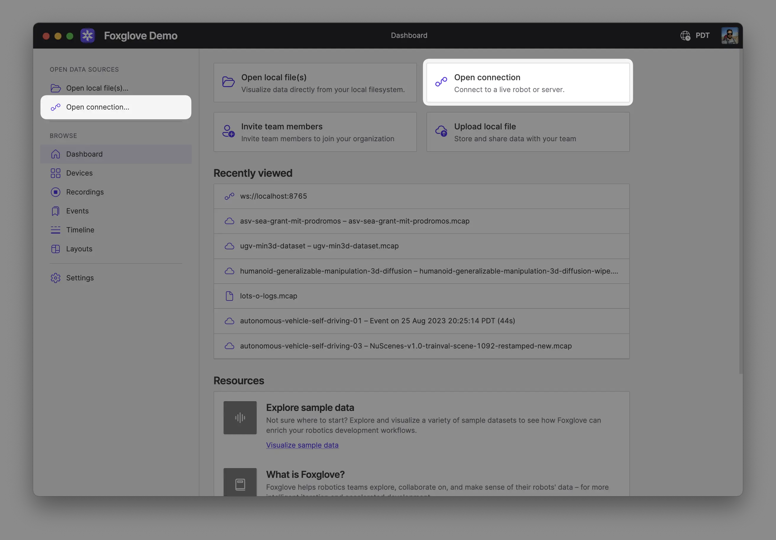
Make sure you are on the same network as your robot. In Foxglove, select Open connection from the dashboard or left-hand menu.
Select Foxglove WebSocket in the Open a new connection dialog, then enter the URL of the server:
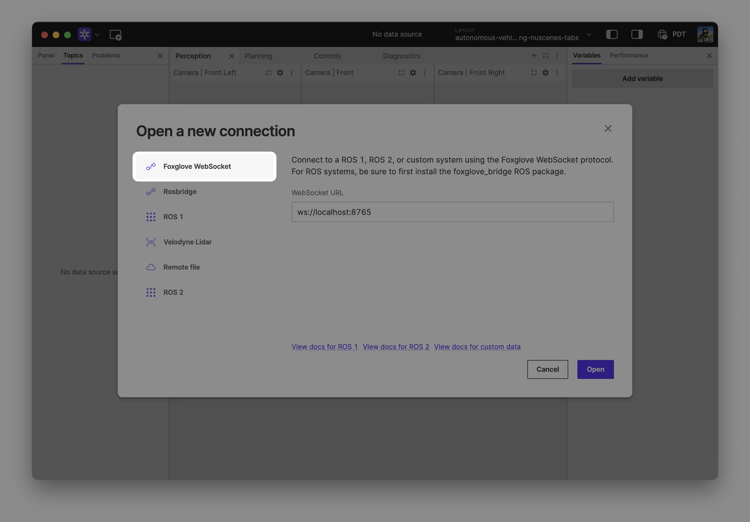
Click "Open" to connect.
Local development: Use ws://localhost:8765 when running the server on the same machine as Foxglove.
Robot connection: Use ws://ROBOT_IP:8765 when connecting to a server running on your robot, where ROBOT_IP is your robot's IP address on the network.
Optionally import the example layout at foxglove/oak_layout.json (in the Python example directory) via Import from file… in the layout menu.
Visualize Camera Feed
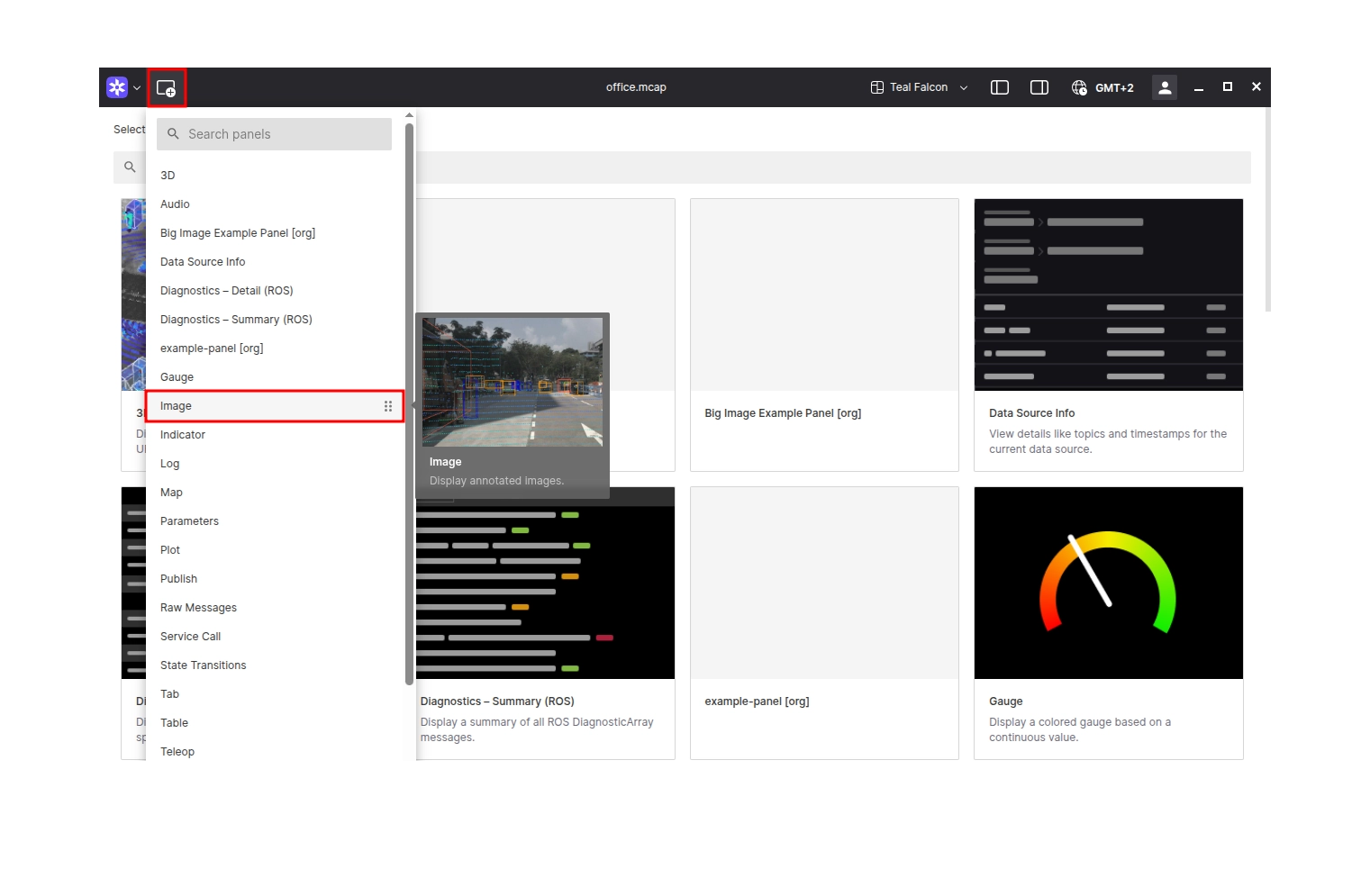
Add an Image panel to your layout by clicking the Add panel button in the top left corner and selecting the Image panel.
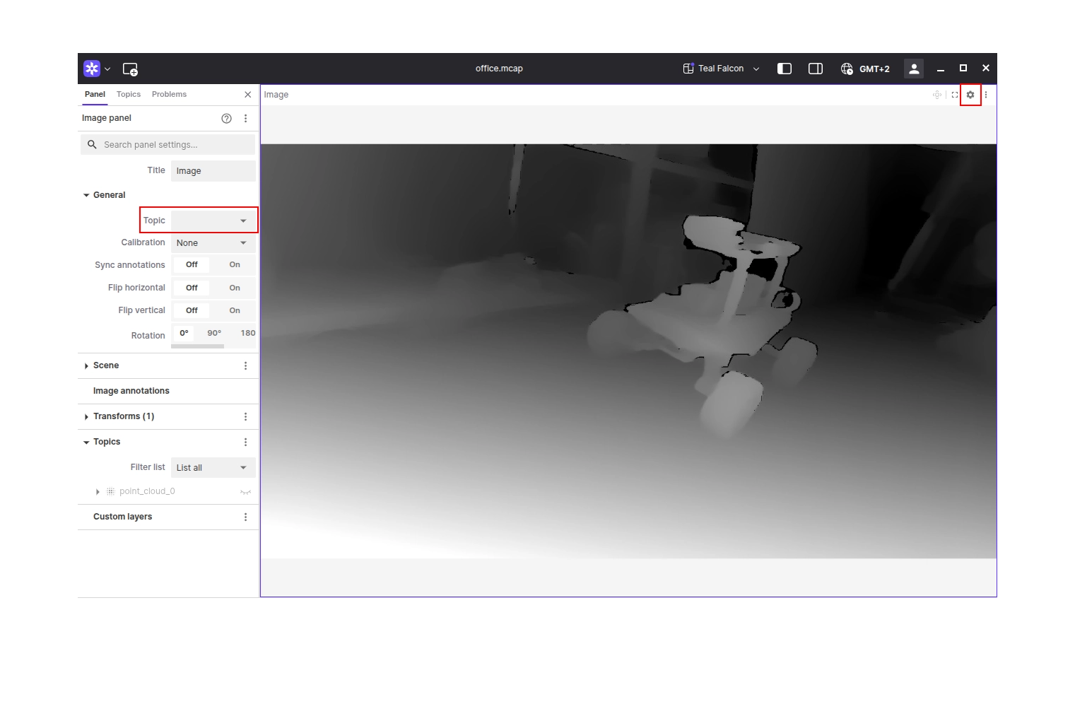
Configure the panel by selecting the appropriate image topic from the Topic dropdown in the panel settings.
Visualize Point Cloud
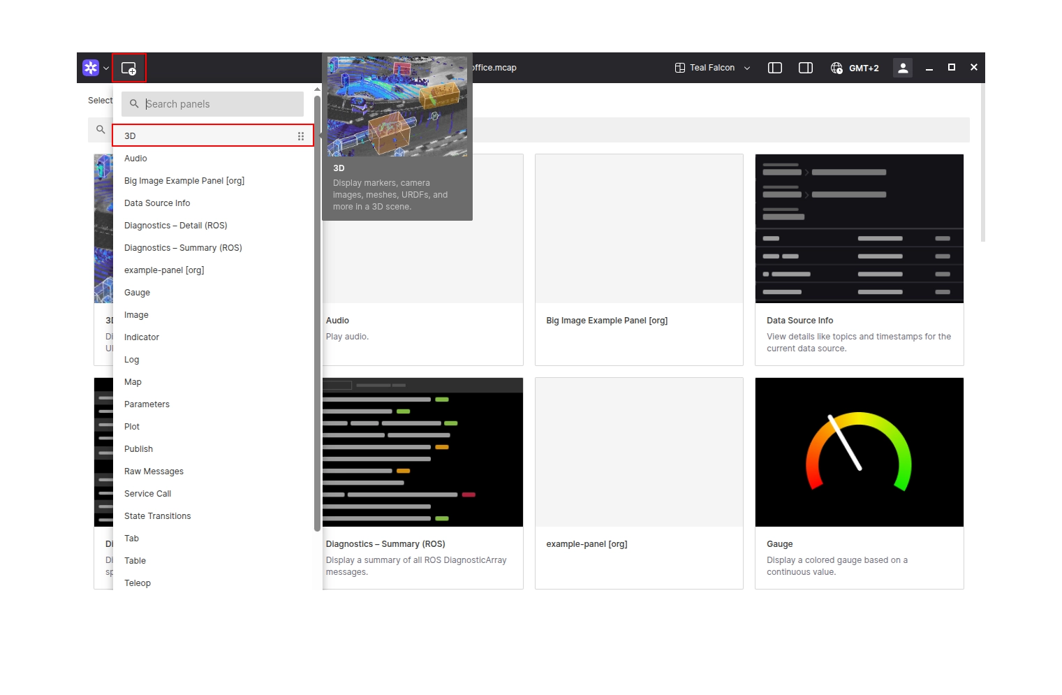
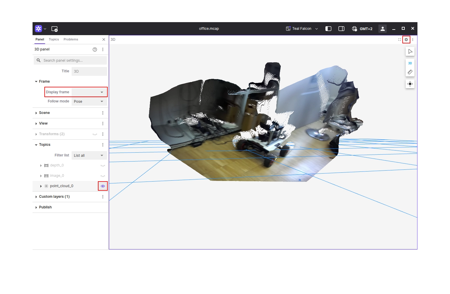
Add a 3D panel to your layout by clicking the Add panel button in the top left corner and selecting the 3D panel.
Visualize IMU Data
The /oak/imu payload is shaped like ROS sensor_msgs/Imu. Add a Plot panel and set the expression to /oak/imu.linear_acceleration.x or /oak/imu.angular_velocity.x (and .y / .z) to chart accelerometer or gyroscope readings over time.
Learn More
- Explore the Python OAK camera streaming example
- Explore the C++ OAK camera streaming example
- Read the Luxonis documentation
- Learn more about using the Foxglove SDK